How to Account for Elevation Differences in Fire Hydrant Flow Tests and Water Supply Evaluations (NFPA 291)

A hydrant flow test is only as useful as the elevation context attached to it. Static and residual pressures are measured at the elevation of the hydrant outlet, not at your building’s connection or sprinkler riser. When those elevations differ, the numbers on the field sheet do not describe the water supply you will actually have for design, ISO rating, or needed-fire-flow comparisons.
Water pressure changes with elevation at a fixed rate: 0.433 psi per foot of rise or drop. A building 200 feet higher than the tested hydrant loses roughly 87 psi from elevation alone. Leave that correction out—or fail to record the differential between residual and flow hydrants—and the supply curve is simply wrong for the site. Elevation adjustment is distinct from friction-loss path corrections; both must be applied before you calculate available flow at 20 psi residual or run hydraulic calculations.
This article walks through the full workflow: what to measure in the field, how to validate residual readings against the elevation delta, how to shift the entire supply curve to design grade, and how to document results so they remain defensible months or years later. The core NFPA 291 procedure does not change; interpretation and usability of the results do.
Why Uncorrected Elevation Makes a Flow Test Unusable for Design
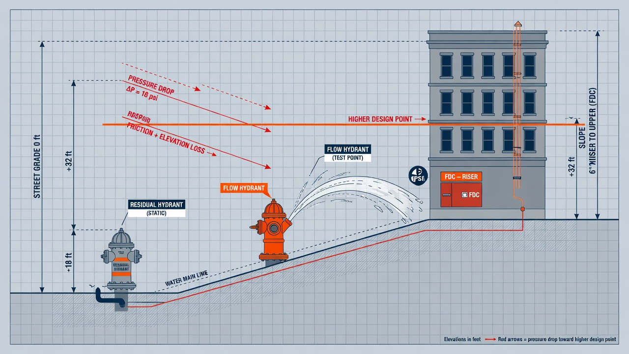
That distinction between procedure and usability is where elevation quietly decides whether a test can support design at all. Static pressure is not an abstract system property floating somewhere in the distribution network. It is the water pressure in the main as measured at the elevation of the hydrant outlet. The gauge reading belongs to that outlet elevation—not to the building finished floor, the sprinkler high point, or the fire-department connection you will later size against.
Because water pressure decreases as elevation increases, every foot of vertical rise drops pressure slightly. Hydrants on higher ground therefore show lower static and residual pressures than those in lower areas. The reverse is equally true: a residual hydrant sitting well below the project will report optimistic pressures that simply will not be there once the data are moved uphill to the design point. Leave those differences unrecorded and the supply curve you plot describes a different hydraulic plane than the one your sprinklers or standpipes will occupy.
Distance compounds the problem. A test taken 500 feet downhill from the project site is not valid for that location—friction losses along the path and elevation both matter. Proximity alone never guarantees transferability; without measured grade change and a clear hydraulic path, the residual reading cannot be trusted as a proxy for available pressure at the point of connection.
The most common way this error enters the record is simple omission. Elevation differential between the flow (test) hydrant and the residual hydrant is a documented common pitfall precisely because it is so often left blank on the field sheet. That single missing datum leaves later reviewers unable to check whether the residual reading is consistent with the static reading, unable to shift the entire supply curve to design grade, and unable to defend available fire flow at 20 psi. Months or years later—when a hydraulic calculation, ISO review, or needed-fire-flow comparison requires a defensible supply—the test is effectively unusable. The numbers may have been precise on the day they were taken; they are simply not transferable to the elevation that matters.
The Three Elevations Every NFPA 291 Test Must Capture
That transferability starts in the field, with three elevations recorded while the gauges are still on the hydrants—not reconstructed later from memory or a rough map. Without them, even a carefully measured flow cannot be shifted to the grade where the building, riser, or FDC will actually sit. Hydrant elevation belongs among the key data points on every flow-test record, on the same field sheet and final report as static and residual pressures, measured flows, C-factors, and the test date, so the supply curve can later be corrected with confidence.
Residual hydrant: the pressure reference
Record the elevation of the residual hydrant first. Static and residual pressures are read at that hydrant’s outlet, so its elevation is the datum for the entire pressure side of the test. Every later comparison—flow hydrants, the project site, the design point—runs against this reference. Treat it as non-negotiable: if residual-hydrant elevation is missing, the pressures themselves have no fixed vertical context.
Flow hydrants: outlet-to-outlet differentials
Record the elevation of each flow hydrant as well. Outlet-to-outlet differences between residual and flowing hydrants let you check whether the observed static pressures make physical sense and explain any gap that is not pipe friction. When a higher flow hydrant shows a static reading that cannot be reconciled with elevation alone, the discrepancy often points to a closed valve, a bad gauge, or a measurement error. Catching that in the field is far cheaper than discovering it during an ISO review or a sprinkler design submittal.
Design elevation: where the supply will be used
Finally, record the design elevation that will receive the translated supply—building finish grade, riser base, fire department connection, or the governing hazard height, whichever controls the hydraulic calculation. That is the elevation to which the whole supply curve will eventually be shifted. Capturing it on the same day as the test removes guesswork months later when the only remaining document is a one-page report and the site has already changed.
Elevations can come from survey benchmarks, GPS, utility maps, Google Earth, or the mapping tools built into modern flow-test software. When precision matters—for a tight residual, a long vertical rise, or a high-rise connection—note the method and the vertical datum on the field sheet. The discipline is simple: residual-hydrant elevation, flow-hydrant elevations, and design elevation travel with the pressures and flows so the next engineer inherits a usable test instead of an orphaned set of numbers.
The 0.433 psi per Foot Rule: Converting Elevation Difference Into Pressure
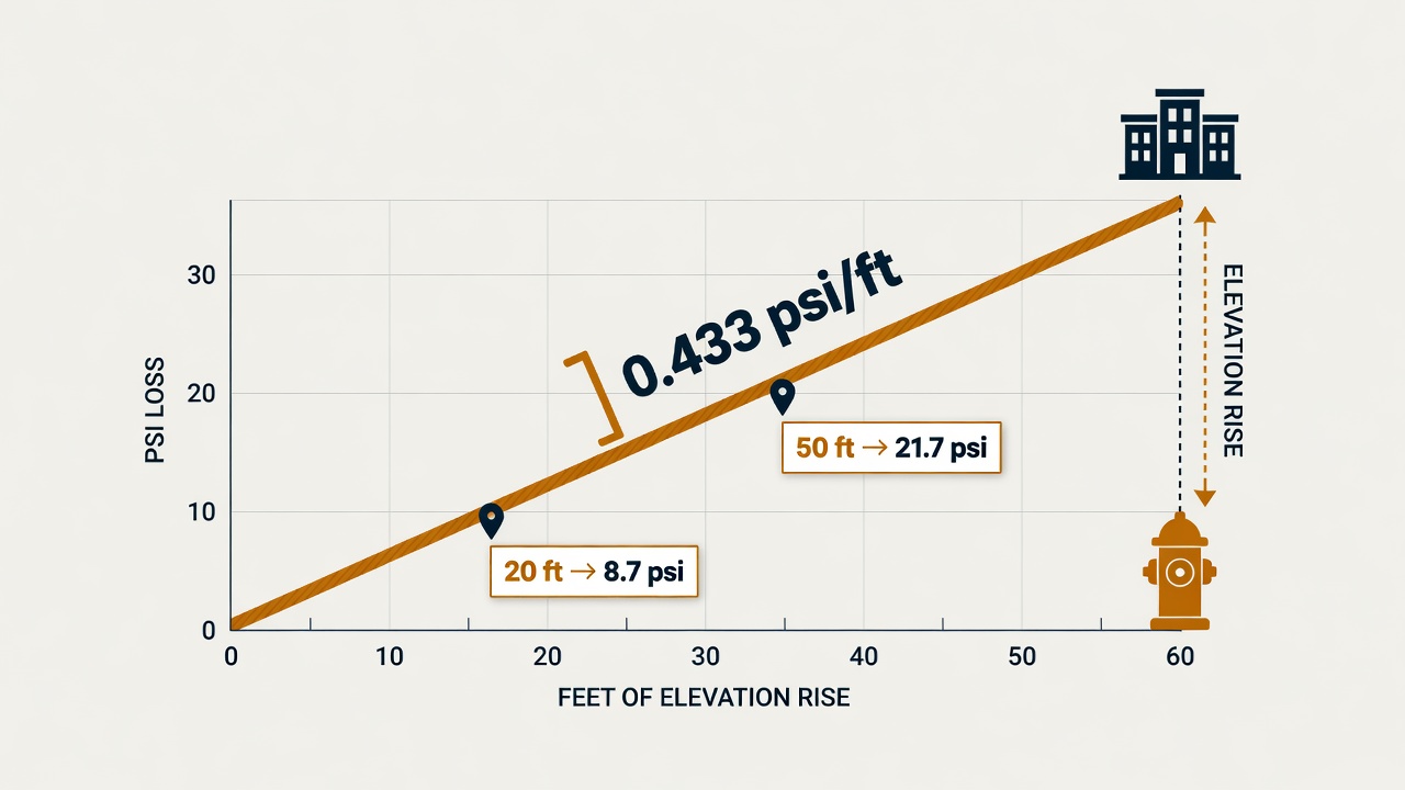
Those three elevations only become useful once you convert the vertical differences into pressure. The relationship is fixed and simple: elevations impact pressures at a rate of 0.433 psi per foot of elevation gained or lost. Each foot of height provides 0.433 pounds per square inch of water pressure. Written as an equation, pressure (psi) equals 0.433 psi/ft times the height difference in feet.
Apply that single factor to both the static and the residual readings whenever you shift the data set from one elevation datum to another. The supply curve moves as a rigid body; orifice calculations and friction losses along the main stay separate. State the reference clearly on the sheet so the next person knows which way the arithmetic ran.
Direction follows the physics of a water column. Correct toward a higher point by subtracting the elevation pressure; correct toward a lower point by adding it. Pressure falls as you climb and rises as you drop—exactly as a standing column of water would behave. Keep the sign convention consistent on every test so residual-to-design and residual-to-flow adjustments never reverse by accident.
Short worked examples
Suppose the residual hydrant sits at elevation 420 ft and the building’s riser base is at 470 ft. The difference is 50 ft upward. Multiply: 50 × 0.433 = 21.65 psi. Subtract 21.65 psi from both the recorded static and residual pressures before you plot available fire flow at 20 psi or run hydraulic calculations at design grade. The entire supply curve has now been relocated to the higher datum.
Reverse the numbers: design elevation 20 ft below the residual hydrant. Difference is 20 ft downward, so add 20 × 0.433 = 8.66 psi to static and residual. The adjusted pair now represents the water supply as it would appear at the lower grade. Field crews and designers who keep one consistent conversion—always 0.433 psi per foot, always applied to the whole curve—avoid the silent mismatches that turn an otherwise good test into unusable numbers. Record the elevation difference and the resulting psi adjustment next to the elevations so the arithmetic stays transparent to whoever opens the file next.
Elevation Delta as a Field QA Check Between Residual and Flow Hydrants
That same elevation difference you just logged is more than a correction factor—it is also one of the quickest quality checks you can run before anyone leaves the site. If residual and flow hydrants sit on the same continuous hydraulic grade line (no intervening closed valves, throttled mains, or gauge error), their static readings must differ by roughly the elevation-derived pressure delta. Static pressure at the higher hydrant should read lower than static at the lower hydrant by that amount; the reverse is true when the flow hydrant is downhill. When the numbers line up, you have independent confirmation that both gauges saw the same system and that the elevations you recorded are usable.
A concrete check makes the expectation clear. A 70 ft elevation difference yields a pressure delta of approximately 30.31 psi. If the residual hydrant is the lower of the two, the higher flow hydrant should read lower by roughly that amount under the same no-flow condition. Small deviations of a few psi are normal—gauge calibration, slight demand on the main, or rounding in the elevation source—but a large unexplained mismatch is a red flag, not a number to average away later in the office.
When the offset is far outside the elevation delta, stop and investigate in the field. Typical causes include a partially closed valve between the hydrants, a bad or incorrectly zeroed gauge, a reading taken on the wrong outlet or with the hydrant not fully open, an elevation transcription error, or even two hydrants that are not on the same pressure zone. Correct the physical condition or retest; do not “smooth” the statics to force the math to work. Treating the elevation QA as a leave-site gate protects everyone who will later use the package for available fire flow, sprinkler supply calculations, or ISO work. Once the statics reconcile with the elevation delta, you can confidently shift the entire supply curve to the design elevation knowing the underlying test is sound.
Shifting the Full Supply Curve to Design Elevation
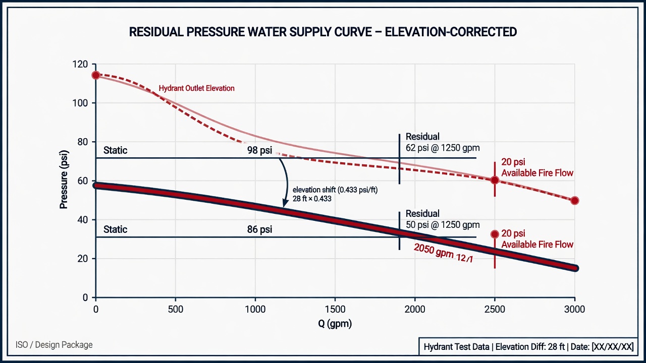
That confidence is earned only when the correction itself is applied the right way. The elevation pressure change is not a static-only tweak. Static and residual must both move by the same 0.433 psi per foot so the supply relationship that the test actually measured stays physically consistent. Correcting only the static reading stretches or compresses the curve and invents a water-system characteristic that never existed in the field. Shift both ends of the pair—and therefore the entire N1.85 curve that connects them—by the identical elevation psi, and the shape of the supply remains true while its absolute elevation changes to match the design datum.
The size of that vertical shift can dominate the usable pressure budget long before pipe friction is considered. On a high site that single correction can drop an apparently healthy residual into the teens, leaving little or nothing for hose streams or sprinkler demand at the design grade. The reverse is equally important: a test taken well above the project can understate available pressure until the curve is shifted downward. Either way, the arithmetic is the same—multiply the elevation difference (design elevation minus residual-hydrant elevation) by 0.433 and apply the signed result to every pressure point on the test curve.
Re-reading available fire flow on the corrected curve
Once the curve sits at the design elevation, available fire flow is re-read at the residual floor the jurisdiction actually uses—commonly 20 psi residual, sometimes a higher local minimum. Because both static and residual have moved together, the flow value that satisfies the residual floor is simply the flow that the original test equation or graph yields after the constant elevation offset is added or subtracted. That corrected flow is the number that belongs in sprinkler hydraulic calculations, needed-fire-flow comparisons, and ISO grading packages. Using the uncorrected field residual for a higher building systematically overstates supply; using it for a lower building understates it.
Final reports must make the translation auditable. Record the field elevations (or elevation differentials) of the residual hydrant, each flow hydrant, and the design datum—building grade, riser base, FDC, or hazard height—alongside the raw static and residual pressures and the corrected values. Note the datum and method used to obtain the elevations. When an AHJ or ISO reviewer can see both the original test geometry and the exact elevation offset applied, the supply curve can be verified or re-shifted without another trip to the street. Elevation correction is still only half the story; friction loss along the path from the test hydrants to the point of connection must be stacked on top of the vertical shift before the design gate is called.
Stacking Elevation Correction With Friction Loss Before You Call the Design Gate
That friction path is not optional, and it is not the same physics as elevation. Elevation correction and friction-loss correction are complementary. One accounts for the vertical head between the residual hydrant and the design datum; the other accounts for the horizontal (and sometimes vertical) run of main, fittings, and service from the supply node you just corrected to the actual point of connection. Using elevation as a stand-in for main friction—or treating a long friction path as if it somehow “covers” a grade change—produces a supply curve that looks tidy on paper and fails under review. Apply both. Do not let one substitute for the other.
A reliable order of operations
Keep the sequence deliberate so each step rests on clean data:
- Establish clean field static and residual pressures at the residual hydrant, with flows and pitot readings documented for every flowing outlet.
- Apply the residual-to-flow hydrant elevation check as field QA and resolve any unexplained mismatch before leaving the street.
- Translate the full supply curve—static and residual together—to the design elevation using the same elevation pressure shift on both points.
- Only then apply pipe friction from that supply node to the point of connection (riser base, FDC, or other design gate), using the actual route, diameter, length, and C-factor you will defend in the hydraulic calculation.
When the elevation-adjusted residual already sits near or below the usable residual floor, available fire flow and sprinkler margins collapse even if the raw street test looked strong. A generous static on the hydrant gauge is irrelevant once the vertical shift has consumed most of the residual band; friction only tightens the remaining room. That is the moment the corrected curve stops being a comfort number and becomes a design constraint.
Use the post-correction residual and available flow to force honest choices rather than hoping uncorrected street data will pass an AHJ or ISO review. If the adjusted curve cannot support the required demand at a safe residual, the options are real: a fire pump, an on-site tank or other stored supply, an alternate connection to a stronger main, or a deliberate reduction in system demand. Document the field elevations, the design datum, the elevation shift applied, and the friction path so a reviewer can reconstruct the gate without another trip to the hydrants. Done in that order, NFPA 291 results remain usable for design instead of becoming a second round of field work after the first submittal is rejected.