
How to Select Residual and Flow Hydrants for Accurate NFPA 291 Flow Tests
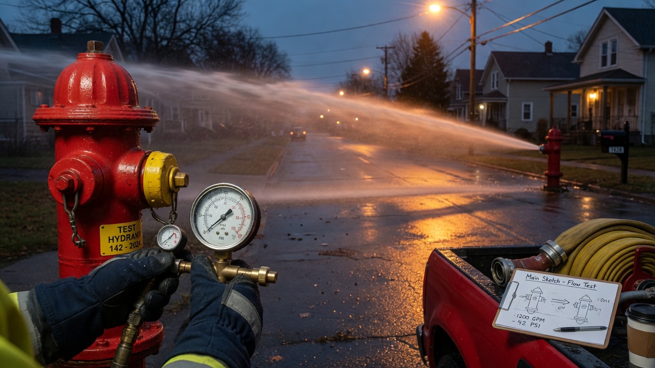
A hydrant flow test is only as good as the two hydrants you choose. Under NFPA 291, one hydrant holds static and residual pressure while another (or more) discharges flow. Pick those outlets by convenience—the closest pair on the same block—and you often measure a local stub or loop effect instead of the main’s real capacity. The numbers look precise; the fire-flow conclusion is wrong.
The fix is layout-first selection. Before you open a nozzle, read the distribution map: main sizes, dead ends, loops, and how water will actually travel from source to the flowing outlet while the residual gauge watches the system. Residual and flow hydrants must sit on the same hydraulic path in a way that the residual drop represents usable capacity at the point of interest—not a pressure blip from a side branch or a throttled service.
This article walks through that pairing method end to end: what each role does in the test, how main layout drives placement, how to avoid common misconfigurations, and how to document a setup that yields defensible, repeatable fire-flow data. If you came here to select residual and flow hydrants the right way, start with the system—not the nearest two barrels.
Why Residual–Flow Pairing Controls Whether NFPA 291 Data Is Usable
That principle is not a preference—it is the difference between a residual reading that tracks the main you care about and one that only looks busy on the field sheet. When you open hydrants for an NFPA 291 test, you are not sampling convenient barrels. You are assembling a temporary hydraulic circuit. The residual hydrant is the observation node, where static and residual pressures are read. The flow hydrant (or hydrants) is the load node, where water leaves the system so the residual can drop. The geometry of the mains between those nodes defines what the pressure drop actually means. If that path is not the main or zone you intend to characterize, the gauges can be accurate and the data still unusable.
Residual placement fails when the observation node sits off the hydraulic path of interest. Put the residual on a different pressure zone and you measure a regulator boundary or a closed zone valve, not the target main. Sit it on a dead-end spur off the feeder and the residual drop reflects local spur losses and dead-end hydraulics rather than capacity along the through main. Park it on an oversized feeder while flow is pulled from a smaller branch and the residual barely moves even when that branch is stressed—so the recorded drop does not represent the location you need to rate.
Flow placement fails the same way when the load node pulls water from the wrong route. A flow hydrant that draws from a parallel path leaves the residual main under-loaded, so residual drop understates demand on the path you care about. Flow taken downstream of a closed or partially closed valve can starve the residual side or force water through unintended routes, overstating or understating available capacity depending on which side of the isolation you read. In every case the instruments may be fine; the circuit geometry is wrong.
This article stays on selection and configuration only: which hydrants form a valid residual–flow pair for a given main layout, how distribution geometry drives that choice, how to avoid common misconfigurations, and how to document a setup that yields defensible fire-flow data. Measurement technique, Hazen–Williams C-factors, graphing methods, and friction-loss math are outside the scope here—they matter, but only after the pair itself is hydraulically correct.
Map the Layout Before You Touch a Hydrant Cap
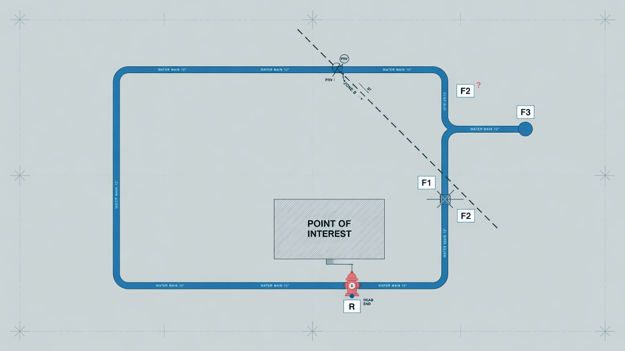
e first practical step is always the same. Pull the distribution map or GIS layer and walk every candidate hydraulic path on paper before anyone loosens a cap. Diameters along the route, whether the feed is looped or dead-end, and the direction water normally travels under demand are not background detail—they define whether a residual reading will reflect true system drop or a convenient fiction.
What the map pass must capture
Trace pipe sizes on every segment that will carry test flow. A residual sitting on a large feeder while flow is pulled from a smaller parallel main understates the drop the protected risk actually sees. A hydrant on a dead-end spur may look close on the street yet sit outside the main path entirely, so the residual never feels the draw. Note normal flow direction under demand as well; pairing against the prevailing path produces a different—and often more representative—drop than pairing with it.
Flag every hydraulic discontinuity that can isolate residual from flow: pressure-zone boundaries, PRV stations, check valves, and normally closed isolation valves. If the two hydrants end up on opposite sides of any of these, the gauge will record a clean number that has nothing to do with the main you intended to test. Record elevation differences between candidates at the same time. Static head change appears as residual drop unrelated to friction under flow; you catch it here so later interpretation does not mistake topography for available fire flow.
Tie the survey to the test objective and field reality
Identify the specific main segment or service address the test is meant to support. That single anchor keeps every later pairing decision from drifting toward whichever outlets happen to be easiest to reach. On the same pass, capture utility and street constraints that will force alternate pairings: out-of-service hydrants, traffic-control limits, safe discharge paths, and any temporary isolation already in place. These routinely eliminate the theoretically ideal pair; documenting them beside the pipe geometry means the next-best hydraulic configuration is chosen deliberately rather than improvised on site.
Once diameters, feed type, flow direction, discontinuities, elevations, objective, and constraints are marked, you hold the information needed to place the residual hydrant where it actually senses the path of interest—not merely the nearest available outlet.
Anchor the Residual Hydrant to the Point of Interest
With that map in hand, residual selection stops being a proximity problem. The residual hydrant is the outlet whose static and residual pressures best represent supply at the design point—whether that is a building connection, a proposed sprinkler tap, or the main segment under evaluation. Its sole job in an NFPA 291 test is to sense the pressure drop the system actually experiences under flow along the path that matters for the decision you are supporting.
Prefer a residual on the same main and in the same pressure zone as the point of interest. Walking distance is irrelevant if a closed isolation valve, a PRV, a check valve, or a zone boundary sits between the residual and the design location. A residual on the far side of any of those discontinuities is reading a different hydraulic world: it may hold steady while the true supply path is dropping, or drop for reasons that never reach the site. Reject it even when it is the nearest operable outlet you can walk to.
Position on the path, not just the zone
Zone membership alone is not enough. The residual should sit between the supply and the flowing hydrants so residual drop reflects friction loss on the evaluated path. When flow is drawn downstream of that residual, the change at the gauge is the drop the design point would see under similar demand. A residual beyond the flow hydrants, or parked on a spur the flowing water never passes, measures a different circuit. The numbers can look precise and still fail to describe the path you care about.
Watch the large-diameter feeder trap. A residual on an oversized transmission main may barely move while the local grid that actually feeds the site is weak. That pairing can look hydraulically healthy on the test sheet and still be invalid for any claim about local capacity. If the residual does not sit on the same hydraulic path the building or segment uses, the residual drop does not support local design decisions—no matter how clean the gauges read.
When the ideal residual is unavailable
If the ideal residual is damaged, buried, or inoperable, choose the nearest substitute that still obeys the same rules: same main or tightly coupled loop, same pressure zone, no intervening closed valve or PRV, and still upstream of the flow draw relative to the point of interest. Document the substitution and the path difference so anyone reading the test later knows what the residual actually represented. Only after that residual is locked in do you turn to placing the flow hydrants that will load the path.
Place Flow Hydrants to Load the Path the Residual Is Watching
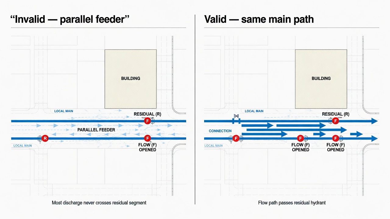
Flow hydrants exist to stress the same hydraulic path the residual is monitoring. Their job is not to produce the biggest pitot reading you can find on the block; it is to pull water across the main segment, service address, or design point you already anchored the residual to. That means the discharge must draw from upstream supply through the residual’s main—not from an independent feeder, a parallel loop, or a strong trunk that never touches the evaluated segment.
Start from the locked residual and walk the map along the intended flow direction. Candidate flow hydrants sit on that same main or on laterals that only receive water after it has passed the residual’s location. If opening a hydrant would let supply arrive from another direction—around a loop, past a closed valve, or off a larger feeder that bypasses the residual—drop it from the list. High combined flow with almost no residual drop is the classic signature of that mistake: the system looks strong on paper while the path you care about barely moved.
Spacing that creates real drop without leaving the path
Spacing is a hydraulic compromise, not a convenience rule. Flow outlets need to be far enough from the residual that friction and demand on the monitored segment produce a meaningful residual drop—enough change to show how the main behaves under load—and far enough that hose lays and discharge streams stay safe for crews and traffic. They also need to stay close enough that the water still travels the intended main rather than detouring onto a parallel grid or a different diameter that no longer represents the design point. When the only operable hydrant sits on a parallel loop, treat that as a failed pairing for this residual, not a workable shortcut.
Outlet and nozzle choices follow the same logic. Plan which ports you will open and what nozzle sizes you will use so the expected draw is large enough to move residual pressure into a useful range for the test, without turning the setup into a friction-loss exercise. The goal is representative system drop on the path under test, not maximum theoretical capacity from every available barrel.
Field constraints will push back. Traffic control, landscaping, drainage paths, parked cars, and restricted discharge directions often rule out the hydraulically ideal outlet. When that happens, choose the next hydrant that still loads the residual’s path, not the nearest one that is merely easy to open. Note the compromise in the test record—why the preferred flow location was skipped and how the alternate still draws across the evaluated main—so later readers can judge whether the residual drop still means what the pairing intended.
Multi-Hydrant Flows and Constrained-Site Pairings
That same discipline applies when one flow hydrant cannot pull enough residual drop. On strong or large-diameter mains a single outlet may leave residual almost flat even at full pitot flow. Adding a second—or, when the main can support it, a third—flow hydrant is the correct response, provided every flowing outlet still draws across the path the residual is watching. All flow points stay hydraulically downstream of (or on the same evaluated segment as) the residual anchor; none may sit on a parallel feeder, opposite side of a loop, or upstream of the residual so that water never crosses the segment of interest. Open outlets in a coordinated sequence, confirm each contributes to the same residual drop, and record which hydrants flowed and in what order.
Dead-end mains versus looped grids
Layout still dictates the pairing pattern. On a dead-end main, place the residual toward the source and the flow hydrant(s) toward the free end so discharge loads the entire evaluated length. On a looped grid, choose flow hydrants that force water across the specific arc or block the residual is monitoring rather than letting supply arrive from the opposite direction and leave residual nearly unchanged. If the grid has multiple open paths, isolate or accept only the routes that keep the residual on the loaded path—and document any temporary valve work.
Tight sites and single-hydrant reality
Some sites offer only one operable hydrant near the point of interest. You can still obtain a static and a flowing residual at that hydrant and a pitot reading from its other outlet (or from a distant flow hydrant if one can be made to load the same path). What you may claim is limited: the result describes supply at that hydrant under the configuration you actually ran, not a clean main-segment capacity or a design-point residual taken from an ideal anchor. State the limitation plainly in the record—single-hydrant or non-ideal path—so the numbers are not later treated as a full NFPA 291 path test.
Selection emphasis also shifts with the test goal. When the aim is main-capacity characterization along a feeder, residual and flow hydrants are spaced to load that feeder and residual drop is interpreted as main performance. When the aim is hydrant or local supply at a specific service location, the residual stays tight to that connection or building tap and flow hydrants are chosen only to stress the local approach mains. Do not blur the two; the pairing that serves one goal can misrepresent the other.
Multiple simultaneous discharges can lower pressure for nearby customers, trip system controls, or draw utility attention. Coordinate with the water utility before opening several nozzles at once—confirm allowable flow windows, notification requirements, and any SCADA or booster-plant implications—so the test stays both hydraulically valid and operationally acceptable.
Configuration checklist before you commit to the pairing
- Every flow hydrant loads the same path the residual is monitoring—no parallel or upstream bypasses.
- Dead-end: residual toward source, flow toward the end; looped grid: flow forces water across the watched arc.
- Added second/third flow hydrants remain downstream/consistent with the residual anchor.
- Single-hydrant or tight-site tests carry explicit caveats on what the data represent.
- Main-capacity pairings versus local-service pairings are chosen and labeled for the actual goal.
- Utility coordination is complete when multiple discharges may affect customers or controls.
Field-Validate the Pairing Before You Open Nozzles
With pairings labeled and utility coordination complete, one short field check still stands between a sound configuration and a misleading NFPA 291 result. Map work and path rules only hold if the hydrants you open still match that path on the ground. Walk the residual and flow units before anyone cracks a nozzle.