How to Perform the New Single-Hydrant Capacity Test

A hydrant flow test used to mean one field picture: open a steamer or side outlet, watch residual fall on a nearby hydrant, and convert that drop into available fire flow on the main. Current NFPA 291 practice still uses that multi-hydrant method when the grid is the unknown. It also defines a narrower test that crews actually run when they have only one hydrant, one gauge set, and a need to know what that hydrant can discharge.
That method is the single-hydrant capacity test. Static, residual, and pitot all belong to the hydrant you are flowing. Done correctly, it answers hydrant capacity, supports marking, and gives a defensible discharge (Q). Done carelessly—or treated as if it were a main-capacity test—it produces numbers that look precise and still fail sprinkler design, ISO review, or a model of the distribution system.
This article is the field playbook for the current method. It covers when NFPA 291 allows a single-hydrant test versus a traditional main-capacity test, the residual rules that replaced a rigid large-drop target, pitot technique, the Q calculation and rated flow at the residual floor, edition points that affect timing and documentation, and the errors that most often skew the result.
When a Single-Hydrant Capacity Test Is the Right Method
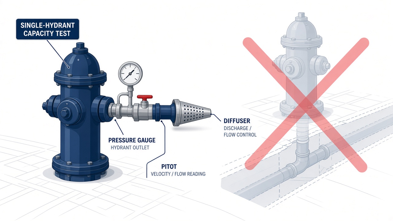
That choice starts with a simple distinction. A single-hydrant capacity test measures performance at one outlet: static pressure, then residual and a pitot reading while that same hydrant is flowing. Those readings describe what the hydrant can discharge, not how the surrounding mains behave as a supply network.
NFPA 291 treats that focused test as the right method when the question is local hydrant performance—private systems, limited access, dead-end laterals, or a targeted check on one outlet. You are asking what this hydrant can put on the street, not what fire flow the grid still has.
A main-capacity test still uses multiple hydrants to characterize system supply and remains the tool for larger design, ISO, and modeling work. The two methods are compared in a companion article rather than restated here.
AHJ acceptance, sprinkler design inputs, ISO grading, and hydraulic models still decide whether those single-hydrant numbers are enough—or whether the grid itself must be measured with a multi-hydrant test.
Running the Test: Setup Through Shutdown
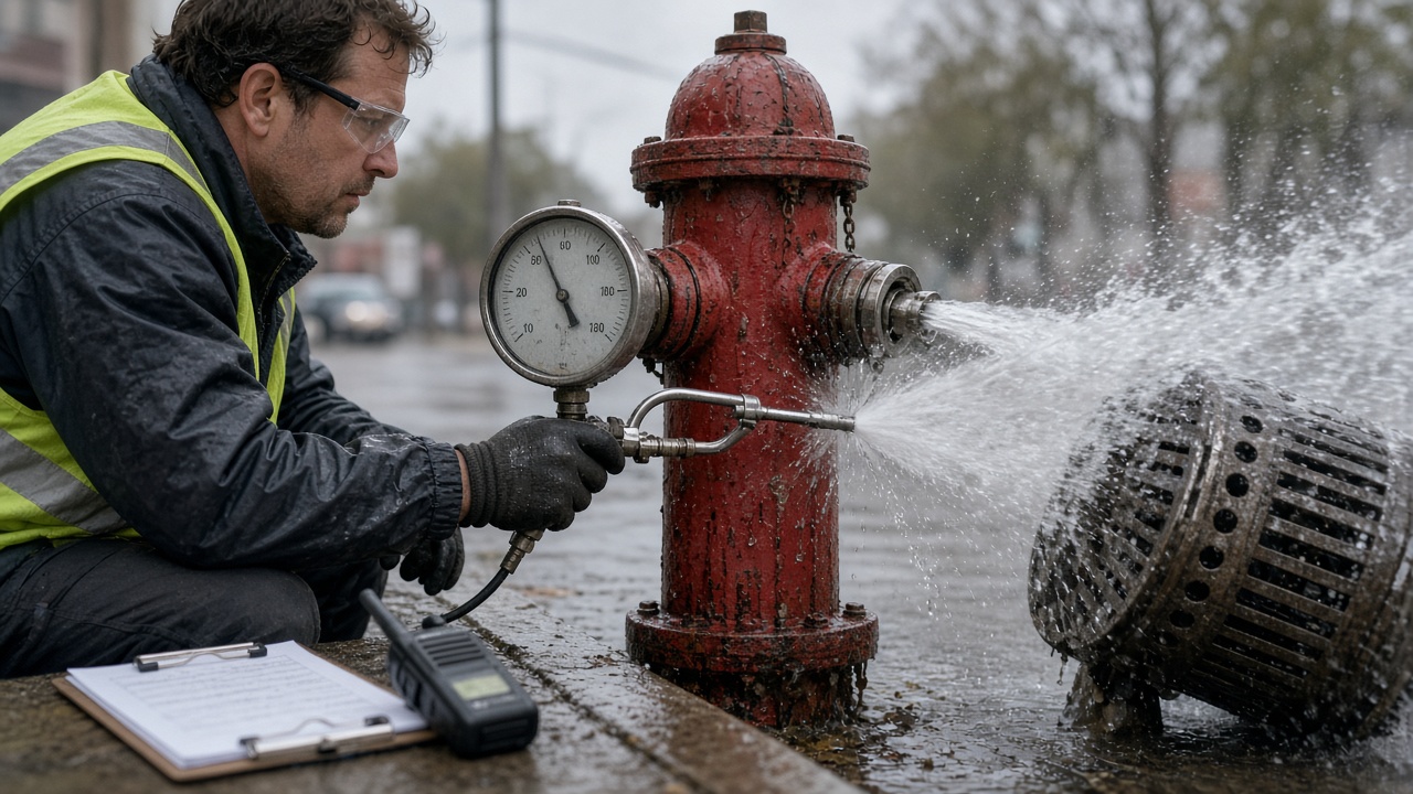
When those numbers are the assignment, the field work is still a short, disciplined sequence: pick a representative hydrant, use calibrated instruments, and write every reading down before anyone leaves the curb.
Choose the hydrant and stage the work
Select a hydrant that stands for the service you need to know: same pressure zone, similar main, and an outlet you can flow without flooding a travel lane or an entrance. Confirm the outlet is sound, the nozzle size is known, and the matching coefficient (C) is on the sheet before anything opens. A damaged thread, a pitted nozzle, or a guessed C will skew discharge even if the gauges are perfect. Stage calibrated static/residual and pitot gauges, a diffuser or hose to aim the stream, PPE, and traffic control so the reading is not rushed.
Notify the water utility and the AHJ as required. Prefer a window that reflects ordinary system demand. An atypical low-demand hour can make the hydrant look stronger than it is when the result will later support design.
Static, flow, pitot, and close
- Record static pressure before any flow from the test hydrant.
- Open the hydrant fully in a controlled manner so the valve is not throttling the stream.
- Measure residual at the same hydrant or at the designated residual point; do not change locations mid-test.
- Take pitot readings in a full, compact stream—blade centered in the vena contracta, correct stand-off from the orifice, no splash or air in the jet.
- Note outlet coefficient (C), nozzle diameter, elevation if the residual point sits well above or below the outlet, and weather or site conditions.
- Shut down slowly to avoid water hammer, restore caps, and document readings, nozzle, C-factor, time, and personnel before leaving the site.
Residual Pressure and Drop: Guardrails for a Valid Test

Capacity on that sheet still depends on the window in which residual was taken. Residual is the pressure you chose not to undercut while the hydrant was wide open.
Hold it at or above the accepted residual floor used in current practice so the distribution system is not pulled into unsafe territory. Crossing that floor can affect customers, weaken protection elsewhere on the grid, and create conditions the test was never meant to produce. If more discharge would drive residual under the floor, stop.
Enough drop to trust, not enough to punish the main
Older habit often forced a large pressure drop so the curve would look decisive. Current practice favors a lower, practical target when it still yields a clear, stable change between static and residual.
- Too little drop leaves static and residual almost indistinguishable, so later extrapolation becomes guesswork rather than measurement.
- Too much drop risks customer impact, an unsafe residual, and a test that no longer represents ordinary demand.
Residual and pitot must be simultaneous and stable after flow has settled. That pair is what discharge and available-flow math will rest on. An unsteady needle, or a residual taken while you are already closing down, belongs on a redo—not in the packet.
From Pitot Pressure to Available Fire Flow at 20 psi
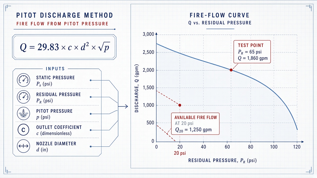
Convert that pitot pressure into discharge at the flowing hydrant before you touch available-flow math. Use the standard pitot discharge formula with the outlet coefficient C, the actual inside diameter of the nozzle or outlet, and pitot pressure. Diameter enters as a square term, and a mismatched C moves the entire result, so use the outlet you actually flowed and the coefficient that belongs to it—not a default from another hydrant.
Rating available fire flow at the residual floor
Measured Q plus the static and residual pair is what NFPA 291-style extrapolation uses to rate available fire flow at the residual floor. Project along the standard logarithmic drop relationship so the reported number sits at that floor, not at the residual you held in the street. Keep pressure, flow, and diameter units consistent unless the AHJ specifies otherwise. Round published discharge and rated flow for reporting, and leave unrounded static, residual, pitot, diameter, C, and Q on the report so a designer can recompute.
Note elevation between the outlet and the gauge and any residual-gauge offset; a few feet of head changes both Q and the extrapolation, so record the difference rather than burying it. The packet should list hydrant ID, date and time of day, nozzle, C, the three pressures, calculated discharge, and available fire flow at the residual floor so AHJs and designers can reuse the numbers.
Edition Notes, Common Errors, and When a Main Test Is Still Required
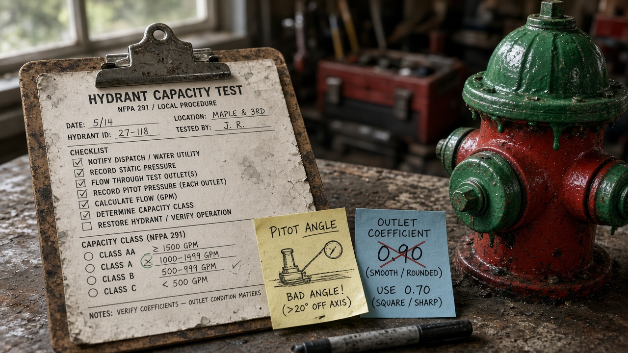
That packet is how you prove the test followed current NFPA 291 practice, not only that the math closed. Recent editions still expect residual at or above the accepted floor, a modest practical drop instead of an older large-drop chase, flow during representative—often peak—demand, and hydrant marking after you rate the outlet. Leave the clause-by-clause deltas to our NFPA 291 edition notes.
Mistakes that skew a single-hydrant result
- Wrong nozzle C-factor
- Off-center or poorly placed pitot
- Residual still moving when discharge is recorded
- Ignored elevation or residual-gauge offset
- Test run at a quiet, non-representative demand
- Incomplete report (missing nozzle, C, time, or the three pressures)
When hydrant capacity is enough—and when it is not
Use the single-hydrant result for local performance, private hydrant assurance, and limited questions that only need that hydrant’s discharge between static and a residual held at or above the accepted floor. Use a multi-hydrant main-capacity test for grid supply, broader ISO work, modeling, or contested design flows; the single-hydrant pair is not a substitute. Compare the methods in our main versus hydrant capacity guide, then train the crew with the pressure-measurement and common flow-test mistakes pieces.