
How to Determine and Apply the Correct Discharge Coefficient (C Factor) in Fire Hydrant Flow Tests (NFPA 291)

Why a Wrong Discharge Coefficient Undermines Every Flow Result
That quantitative effect is where the stakes become clear. Because the discharge coefficient C multiplies straight through the hydrant flow equation, any mistake in selecting it scales the calculated gallons per minute linearly and then carries forward into the available fire flow extrapolated to 20 psi residual. Using the correct coefficient of discharge is critical for accurate results; using the wrong coefficient is the most common source of flow error. A 0.10 miss—reporting 0.80 when the outlet actually warrants 0.90, or the reverse—shifts every subsequent number by more than ten percent. The reported test flow is wrong, the residual-pressure curve is wrong, and the final available-fire-flow figure used for sprinkler design, hydrant color coding, and system capacity decisions is correspondingly overstated or understated.
The practical safeguard begins with outlet choice. Whenever residual pressure and site conditions allow, flow the 2½-inch outlets rather than the pumper nozzle. The 2.5” outlet(s) will give you a more accurate reading in most cases, as the entire cross-section of the outlet is filled by the discharge of water, whereas a pumper outlet often has a void space. That solid jet lets the standard coefficient (0.90 smooth, 0.80 square, 0.70 projecting) stand alone. Pumper streams, by contrast, frequently require an extra velocity-head correction drawn from the NFPA 291 tables, introducing another opportunity for error if the base geometry is already misidentified.
Once the wrong C is locked in, no amount of careful pitot technique or precise residual measurement can recover the true capacity. The arithmetic that follows is simply trustworthy or untrustworthy according to that single multiplier. Mastering the coefficient therefore is not a preliminary nicety; it is the gate that keeps the entire test from cascading into misleading available-fire-flow numbers.
How the Discharge Coefficient Fits the NFPA 291 Flow Equation
Once that gate is open, the path runs straight through the single expression NFPA 291 uses to turn a pitot reading into gallons per minute. The coefficient is not an optional refinement bolted on afterward; it is baked into the formula as a permanent multiplier, so every term must be known with equal care before the arithmetic begins.
In plain language the equation is Q = 29.83 × C × d² × √p. Q is the calculated discharge in gallons per minute. The constant 29.83 converts the mixed English units into a coherent flow rate. C is the dimensionless discharge coefficient that accounts for the vena-contracta and friction losses created by the outlet’s internal geometry. d is the true inside diameter of the outlet in inches, and p is the velocity pressure, in psi, read at the center of the stream with a pitot blade or tube.
Measure the actual bore, not the nominal size
Because d is squared, even a small error in diameter produces a noticeably larger error in Q. Hydrant outlets can differ from their nominal 2½-inch or 4½-inch labels. A quick internal caliper or precision ruler measurement of the clear bore—taken after the cap is removed and before the test begins—is therefore mandatory. Record that measured value, not the stamped size, on the field data sheet; the formula has no provision for “close enough.”
Keep pitot pressure inside the reliable band
The square-root term is well-behaved only when the pitot pressure itself sits in a practical range. For standard 2½-inch outlets the sweet spot is roughly 10–30 psi; below 10 psi the gauge resolution becomes coarse and the stream can wander, while above 30 psi the hydrant is being pushed harder than necessary and downstream residual pressures drop too far for a clean available-fire-flow calculation. When a bare pumper outlet must be used, the lower band of 5–10 psi is preferred so that the additional velocity-head correction later sections will apply remains modest and stable. Opening additional outlets or throttling a gate valve upstream of the test outlet is the usual way to land inside these windows without changing the coefficient itself.
With C, measured d, and a pitot pressure held inside the preferred band, every subsequent correction—whether for a pumper nozzle or a multi-outlet layout—rests on numbers that already deserve confidence. The formula is then ready for the field identification step that assigns the correct numerical value of C.
Feeling the Outlet: Classifying Geometry by Touch
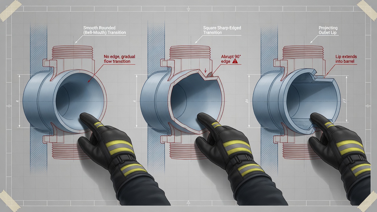
That field identification step begins at the hydrant itself. Before any value of C is written down, the tester reaches into the outlet and feels the transition from the hydrant barrel to the nozzle. The contour under the fingertips is what assigns the coefficient; nothing else substitutes for it.
With a gloved hand inserted past the threads, move slowly from the barrel wall outward toward the nozzle face. The shape of that short transition—smooth curve, abrupt edge, or protruding lip—places the outlet into one of the three NFPA classes used for openings under four inches.
What each contour feels like
A rounded outlet presents a continuous, gentle radius. The metal flows without a catch from the barrel into the nozzle; the fingertip never meets a corner. Most modern hydrants have a smooth rounded transition yielding a coefficient of approximately 0.90, but not all of them do. The shape of the barrel-to-outlet transition still has to be verified on every hydrant.
A square (or sharp) outlet stops the finger with a clean 90-degree edge. There is no radius; the barrel wall meets the nozzle face at a distinct corner that can be felt all the way around the circumference.
A projecting outlet is unmistakable: the nozzle pipe itself extends a short distance into the barrel. The finger first encounters a raised lip or tube before it can reach the outer face of the outlet. That inward projection creates the highest turbulence of the three geometries and therefore the lowest coefficient.
Why the touch test cannot be skipped
A frequent field shortcut is to glance at a relatively new hydrant and assume the outlet is smooth and rounded. That assumption produces the wrong C more often than most crews realize. Age, manufacturer, and even replacement of a single nozzle can leave a square or projecting transition in place. Because the coefficient multiplies straight through the flow equation, the only reliable practice is to feel every outlet that will be flowed and to record the geometry on the test sheet before the pitot gauge is ever placed in the stream.
Standard C Values by Geometry—and When Equipment Changes Them
Once the transition has been felt and recorded, the next step is simply to match that geometry to the coefficient NFPA 291 assigns it. For every outlet smaller than 4 inches the standard values are fixed and unambiguous:
- Smooth and rounded entrance — C = 0.90
- Square and sharp (abrupt 90-degree) edge — C = 0.80
- Projecting into the barrel — C = 0.70
These three figures already account for the friction and vena-contracta losses that accompany each shape, so no further geometric adjustment is required when the pitot is held in a bare hydrant nozzle. Write the chosen C directly on the test sheet beside the outlet description; that single number will multiply every subsequent gpm and available-fire-flow calculation.
Stream straighteners and flow tubes
When a flow tube or stream straightener is screwed onto the outlet, the internal vanes suppress turbulence and the coefficient rises. NFPA 291 therefore suggests C = 0.95 unless the manufacturer has published a specific value for that device. Using 0.95 in place of the bare-outlet figure is the only change needed; diameter and pitot pressure are still measured in the usual way.
Pumper Outlets: Base C Plus the Velocity-Head Correction
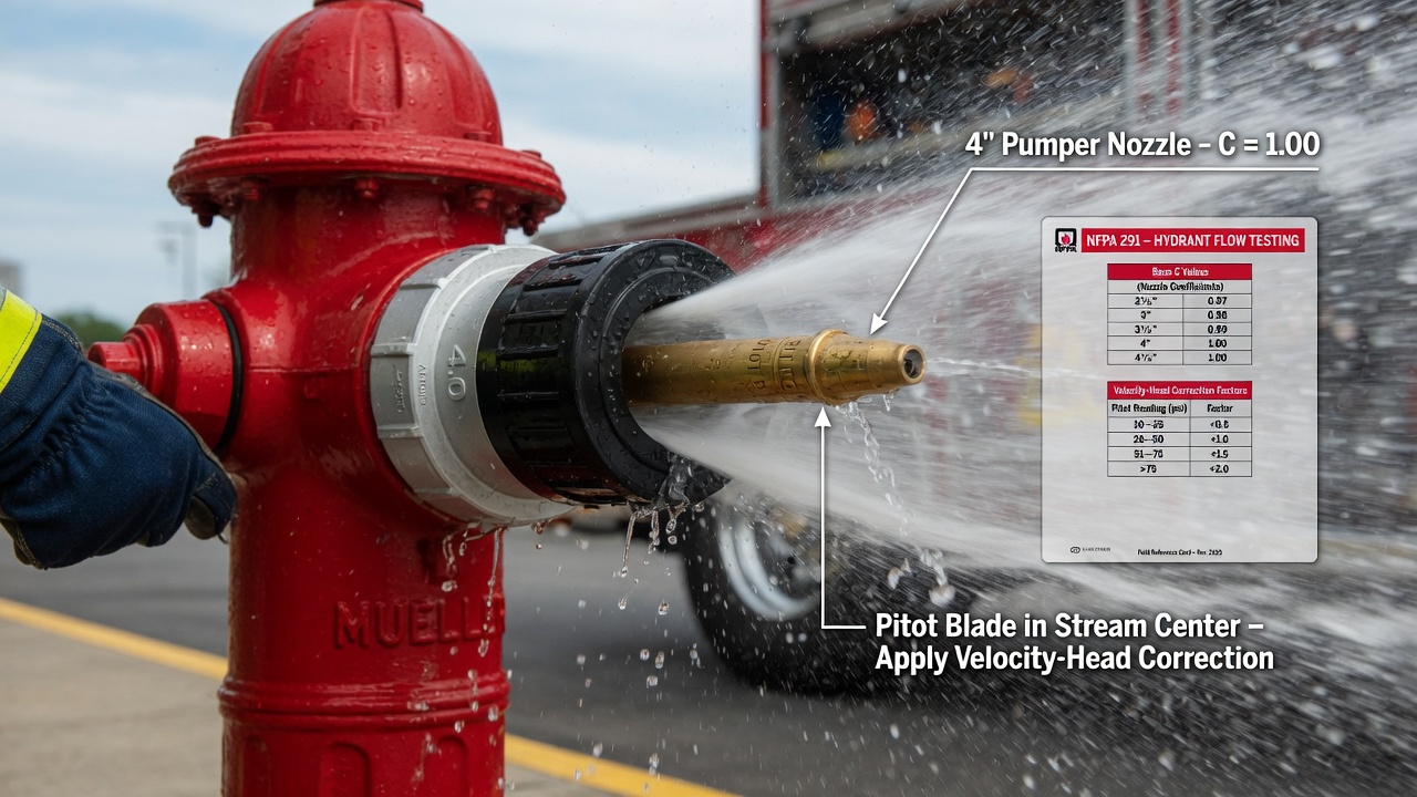
That same principle—match the coefficient to the hardware that is actually flowing—takes on one more layer when the open outlet is a pumper port. Outlets four inches and larger almost never discharge a fully solid jet. Air voids and internal turbulence mean the effective flow area is smaller than the measured inside diameter, so the ordinary geometric C is necessary but not sufficient. NFPA 291 therefore requires a second, velocity-head-dependent factor applied after the basic flow equation has already been solved.
Why a bare pumper stream needs two coefficients
On a 2½-inch nozzle the water column usually fills the entire cross-section, so the single geometry-based C (0.90 rounded, 0.80 square, 0.70 projecting) is enough. A bare pumper outlet behaves differently. Friction and incomplete contraction still depend on the barrel-to-nozzle transition, so the tester first selects the matching base C and computes Q = 29.83 × C × d² × √p exactly as before. That intermediate result is then multiplied by an additional coefficient taken from the NFPA 291 pumper-outlet table—the factor that corrects for the non-solid character of the large stream. The table is keyed solely to pitot (velocity-head) pressure; higher pitot readings produce lower correction factors because the voids become relatively more pronounced.
Table values and the multiply-after-Q sequence
Representative coefficients from the NFPA table for average-type hydrants run as follows:
| Pitot pressure (psi) | Pumper correction factor |
|---|---|
| 2 | 0.97 |
| 3 | 0.92 |
| 4 | 0.89 |
| 5 | 0.86 |
| 6 | 0.84 |
| 7 and over | 0.83 |
The arithmetic order is fixed: finish the base formula first, then scale. Suppose a four-inch pumper outlet yields a pitot reading of 6 psi and the formula (using the appropriate base C and measured inside diameter) returns 1,050 gpm. That figure is next multiplied by the table factor 0.84, giving a corrected discharge of 882 gpm. At 7 psi or higher the factor drops to 0.83; at the low end of the scale a 2 psi reading still requires a 0.97 multiplier. Omitting the second step leaves the reported flow systematically high and, because available fire flow at 20 psi residual scales directly with Q, overstates system capacity by the same percentage.
Preferred pitot band for bare pumper ports
When no flow tube or stream straightener is fitted, NFPA 291 notes that the most reliable results occur with pitot pressures held between 5 psi and 10 psi. In that band the correction factors are well-defined, gauge resolution is comfortable, and the stream remains stable enough for a clean centerline reading. If the single pumper outlet drives the needle above 10 psi, open additional smaller outlets to share the flow and bring the pumper pitot back into the preferred window—then apply the matching table factor to the pumper Q only. Record both the base C and the velocity-head coefficient on the data sheet so any later reviewer can reconstruct the full calculation.
Worked Multi-Outlet Example—and the Cost of Getting C Wrong
With those values logged, the full test reduces to a clean sum of each outlet’s contribution—every one built from its measured inside diameter, the geometry- or device-based C, and its own pitot pressure. The numbers below walk through a representative two-outlet test so the arithmetic (and the leverage of C) is visible end-to-end.
Two rounded 2½-inch outlets, correct coefficients
Both nozzles feel smoothly rounded at the barrel transition, so each receives C = 0.90. Calipers confirm a true inside diameter of 2.50 in on both outlets. Opening the second outlet holds the pitot needles at 16 psi and 14 psi—comfortably inside the preferred band. Residual pressure during flow is 42 psi, which will later feed the available-fire-flow calculation at 20 psi.
| Outlet | d (in) | C | Pitot (psi) | Q (gpm) |
|---|---|---|---|---|
| 1 (rounded) | 2.50 | 0.90 | 16 | 671 |
| 2 (rounded) | 2.50 | 0.90 | 14 | 628 |
| Total discharge | 1,299 | |||
Each line uses the NFPA 291 formula Q = 29.83 × C × d² × √p. The two streams add directly to 1,299 gpm. That total, paired with the observed residual, becomes the input for the available-fire-flow projection at 20 psi.
Same data, wrong C—quantifying the error
Re-run the identical diameters and pitot pressures but assign the square-outlet coefficient C = 0.80 instead of 0.90. Every Q scales by the ratio 0.80/0.90, cutting the total to 1,155 gpm—a 144 gpm shortfall. Because available fire flow at 20 psi residual is derived directly from the test flow, the same percentage error appears in the final reported capacity. A 0.10 miss in C therefore moves both the raw gpm and the design value that sprinkler engineers and fireground officers will rely on.
Closing discipline that keeps every future test solid
Open additional outlets when a single stream pushes pitot pressure outside the preferred band. Record the felt geometry (or manufacturer device type) and the exact C applied for each outlet on the NFPA data sheet so any later reviewer can reconstruct the arithmetic without guesswork. When those habits sit on top of a correctly chosen discharge coefficient, the flow test becomes a trustworthy foundation for hydrant marking, system design, and operational decisions.