
Main Capacity vs. Hydrant Capacity Flow Tests Under NFPA 291: Procedures, Differences & When to Use Each

When you need reliable fire-flow numbers, the test method itself determines whether the result is useful. NFPA 291 draws a clear line between two separate procedures: a main capacity flow test that evaluates water supply available in the main at the residual hydrant location, and a hydrant capacity flow test that evaluates flow available through a single hydrant. The 2022 edition of the standard underscored that distinction so practitioners stop treating them as interchangeable.
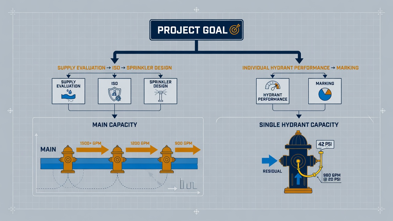
A main capacity test uses a residual (test) hydrant for static and residual pressures plus one or more separate flow hydrants. Results support sprinkler system design, ISO grading, and network capacity decisions. A hydrant capacity test uses the same hydrant for both residual and flow measurements; it is simpler and appropriate for marking or verifying that individual hydrant, but it does not represent true main supply. Neither NFPA nor AWWA recommend the single-hydrant method when the goal is available water for firefighting.
This guide walks through the procedures side by side, the calculations (discharge formula, coefficients, and rated capacity at 20 psi), the pressure-drop targets that make extrapolation reliable, and the practical decision criteria for choosing each test. You will leave knowing which layout to run, how to document it, and how the numbers apply downstream.
Why NFPA 291 Draws a Hard Line Between Main Capacity and Hydrant Capacity
That distinction did not always sit so cleanly in the field. For years, crews ran “a hydrant flow test” without a shared vocabulary for what the numbers were actually supposed to represent. The result was a steady stream of reports that mixed system supply data with single-hydrant performance data—and then treated the two as interchangeable. In the 2022 edition, NFPA 291 clarified two separate and distinct flow tests: one that measures available water supply in the main, and one that evaluates flow deliverable through an individual fire hydrant.
Main capacity testing (the multi-hydrant layout) answers a system question: how much water is available in the water main at a chosen residual location once flow is established elsewhere. Those figures feed sprinkler design, ISO grading, and available-fire-flow calculations. Hydrant capacity testing (the single-hydrant layout) answers a different question: how much water can that one hydrant actually put on the ground through its own outlets, barrels, and internal path. Those figures drive hydrant marking and local performance checks. Blur the two and you produce invalid available-fire-flow numbers for design or rating work, and you mark hydrants with capacities that do not match what the device can deliver.
Before either procedure starts, everyone on the crew needs the same three pressure readings in plain language. Static pressure is the water-main pressure under normal, non-flowing conditions. Residual pressure is the main pressure measured while water is flowing. Pitot pressure is the velocity (flow) pressure taken at the outlet stream itself. Those three terms are the common measurement language for both tests; once they are fixed, the layouts diverge and the calculations stay honest.
Choosing the Right Test for Your Goal
With static, residual, and pitot pressure locked in as the shared vocabulary, the next decision is which layout those readings will feed. The choice is not a matter of preference or crew size—it is driven entirely by the deliverable you need when the test is over.
Match the test to the question you must answer
Select a main capacity (multi-hydrant) test when the goal is available fire flow in the water main at a residual reference point. That is the number required for sprinkler hydraulic calculations, ISO grading, or system supply verification at a site. The residual hydrant stays closed for pressure readings while one or more separate hydrants are flowed, so the result describes what the distribution system can deliver, not what one outlet can pass.
Select a hydrant capacity (single-hydrant) test when the goal is individual hydrant performance—outlet condition, internal friction loss, or color-code and marking verification. Here the same hydrant supplies both residual pressure and the pitot reading, so the result speaks only to that hydrant’s discharge capability under the conditions of the day.
Neither NFPA nor AWWA recommend the single-hydrant method when the true question is water available for firefighting supply evaluation; two or more hydrants are required for that purpose. Treating a hydrant-capacity number as system fire flow produces optimistic, non-conservative design data and incorrect markings.
Decision inputs that settle the choice
- How many hydrants are accessible and can be operated safely at the same time
- Whether results must reference the standard 20 psi residual for available fire flow
- Whether the numbers will feed design software and ISO submissions or only local marking charts
- Any stated preference from the authority having jurisdiction (AHJ) or water purveyor
NFPA 291 recommends that public fire hydrants be flow-tested every five years to verify capacity and marking. Use that cycle as a reminder to pick the test type that matches the verification purpose—main capacity when the system’s available supply is under review, hydrant capacity when the individual unit’s performance and color code are what must be confirmed. Once the goal is clear, the field layout and calculation path follow without ambiguity.
Main Capacity Test: Multi-Hydrant Layout and Field Execution
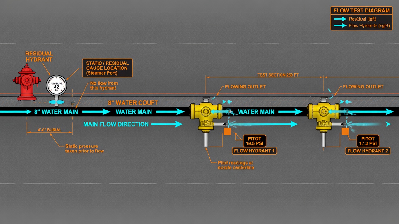
For a main capacity test, that layout begins with two or more hydrants chosen to evaluate the water supply available in the fire main at a residual point. One hydrant serves strictly as the residual (or test) hydrant: it carries the gauges that record static pressure before any water moves and residual pressure once flow is established. One or more separate flow hydrants sit downstream or on the same main; their outlets discharge the water whose pitot readings will later be converted to flow.
Field sequence is deliberate. First record static pressure at the residual hydrant with every outlet still closed. Open the flow hydrant(s) slowly—never slam valves—to avoid water hammer. Once streams stabilize, capture residual pressure at the test hydrant and pitot pressure at each flowing outlet at the same moment. The goal is a meaningful drop from static to residual so the later extrapolation to 20 psi residual stays reliable; classical practice looks for at least a 25 percent drop (or roughly 10 psi). If the drop is too small, open additional outlets or bring another flow hydrant online rather than forcing a single nozzle to extreme velocity.
Pitot readings themselves should land in the practical 10–30 psi band whenever possible. Readings below 10 psi or above 30 psi introduce larger measurement uncertainty, so the preferred fix is simply to add discharge area—more outlets or more hydrants—until the needles settle in that range. Position the pitot blade in the center of the stream roughly half an outlet diameter from the face, and note the exact outlet diameter and type (rounded, square, or projecting) so the correct coefficient can be applied later.
While the gauges are live, document everything the calculation will need: elevations of residual and flow hydrants, horizontal distances between them, outlet diameters, nozzle coefficients, gauge serial numbers, time of day, and approximate system demand conditions. Those notes turn raw pressures into a defensible rated capacity at the residual point—the number sprinkler designers, ISO graders, and system owners actually use. Close every hydrant slowly, restore the street, and the main-capacity data set is complete.
Hydrant Capacity Test: Single-Hydrant Layout and Field Steps

With the multi-hydrant data set closed out, the hydrant-capacity procedure flips the layout: residual and flow collapse onto the same unit so the test measures what that hydrant alone can deliver. One outlet (or a dedicated cap port) carries the pressure gauge while another outlet is opened and pitot-read, or a specialized diffuser/gauge assembly lets residual and pitot be taken simultaneously on the same barrel. The point is no longer the main’s available supply at a remote residual location—it is the volume that individual hydrant can push through its own barrel, stems, and outlets once friction losses inside the hydrant itself are included.
Field execution stays disciplined even though logistics shrink. Record static pressure first with every outlet capped. Open the chosen discharge outlet slowly, seat the pitot blade in the center of the stream roughly half a diameter out, and capture residual and pitot readings together. Keep discharge coefficients matched to the outlet geometry (rounded, square, or projecting) so the calculated flow reflects real nozzle performance. Close the hydrant slowly to avoid water hammer, the same rule that protects mains in the multi-hydrant test. Because only one hydrant is disturbed, setup is faster, traffic control is lighter, and fewer personnel are needed—yet the trade-off is absolute: the number you obtain describes that hydrant’s delivered capacity, not system fire flow.
Document the outlet sizes, coefficients, static/residual/pitot values, and any elevation notes exactly as you would for a main-capacity run, then label the result clearly as hydrant capacity. Those figures support performance verification, color-coded marking, and maintenance decisions. They must not be substituted for the multi-hydrant available-fire-flow number that sprinkler designers and ISO graders require. Used inside that boundary, the single-hydrant test is the efficient, correct tool for confirming what one hydrant can actually deliver.
Matching Results to Sprinkler Design, ISO Ratings, and Hydrant Marking
That boundary matters the moment results leave the field. Main-capacity and hydrant-capacity numbers can look similar on a clipboard—both report a flow tied to a residual pressure—but they answer different questions and feed different decisions. Using the wrong figure is how design packages get undersized and how hydrants get painted with a class they never earned.
Rated main capacity at 20 psi residual is the input sprinkler designers compare against system demand, the number used to confirm fire-flow adequacy for a site, and the figure many ISO grading evaluations expect when awarding hydrant credit. It represents supply available in the water main at the residual location after the friction losses created by the flowing hydrants, then extrapolated to the standard residual reference. That is the only number that belongs in hydraulic calculations and system-level adequacy checks.
Hydrant capacity results stay with the individual unit. They tell you whether that hydrant’s outlets, valves, and internal path are delivering what they should, and they drive the NFPA 291 color classification painted on the bonnet or caps. A strong main can still feed a weak hydrant; the single-hydrant test is what catches that condition. Those results support performance verification and marking—nothing more.
| Application | Correct test | Why |
|---|---|---|
| Sprinkler demand comparison / hydraulic design | Main capacity (multi-hydrant) | Rated flow at 20 psi reflects available supply in the main |
| Fire-flow adequacy / ISO hydrant credit | Main capacity (multi-hydrant) | Graders and AHJs need system supply, not one outlet’s delivery |
| Individual outlet performance check | Hydrant capacity (single-hydrant) | Captures friction and condition of that hydrant alone |
| NFPA 291 marking / color classification | Hydrant capacity (single-hydrant) | Class is assigned from what that hydrant actually flows |
Never substitute a single-hydrant capacity number for available main supply in hydraulic calculations or insurance grading. Designers and graders who receive an unlabeled flow figure have no reliable way to know which test produced it, and the wrong number either understates or overstates true system capability.
Across both tests, 20 psi residual remains the standard reference point when reporting rated capacity. It is widely accepted as the minimum residual pressure at hydrants for effective firefighting and to prevent backflow contamination—so field readings are extrapolated to that level rather than left at whatever residual happened to be observed during the test.
Package every report so the test type cannot be misread: state plainly whether the work was main capacity (multi-hydrant) or hydrant capacity (single-hydrant), identify the residual and flow hydrant(s), include static, residual, and pitot readings, and show the rated flow at 20 psi. Clear labeling keeps AHJs, designers, and ISO reviewers from treating one result as the other.
The Math Both Tests Share: Discharge, Rated Flow at 20 psi, and Quality Checks
Those same static, residual, and pitot readings feed identical formulas whether the crew ran a multi-hydrant main-capacity test or a single-hydrant capacity test. The arithmetic does not change; what changes is which physical layout produced Q, S, and R—and therefore what the resulting available fire flow is allowed to represent.
Discharge from the pitot reading
Flow through each outlet is calculated with the core discharge equation Q ≈ 29.83 × C × d² × √P, where d is the internal outlet diameter in inches and P is the pitot (velocity) pressure in psi. The coefficient of discharge C is taken from outlet geometry:
- 0.90 for smooth, rounded outlets smaller than 4 in
- 0.80 for square or sharp edges
- 0.70 for projecting nozzles
- approximately 0.95 when stream straighteners or flow tubes are fitted
For pumper outlets 4 in and larger, an additional velocity-pressure correction must be applied to Q so the higher exit velocities are not overstated. At a velocity pressure of 6 psi, for example, the factor is 0.84; other tabulated factors are used at other pitot readings. Using the wrong C or skipping the pumper correction is one of the most common ways a clean field test produces a misleading published number.
Extrapolating to rated capacity at 20 psi
Once total test discharge Q is known, rated capacity—available fire flow at the standard 20 psi residual—is obtained from the relationship AFF = Q × ((S − 20)0.54) / ((S − R)0.54), where S is the static pressure and R is the residual pressure recorded at the residual hydrant. The 0.54 exponent makes the result sensitive to the size of the pressure drop; a test that barely moves the residual gauge cannot be extrapolated with confidence.
Because the formulas themselves are shared, the only legitimate distinction is the layout that generated the inputs. A main-capacity (multi-hydrant) AFF may be reported as water available in the main at the residual point and used for sprinkler design or ISO credit. A hydrant-capacity (single-hydrant) AFF may be used only for that hydrant’s performance check and color marking; it must never be substituted for system supply.
When to reject or re-run before publishing
Before any number leaves the field book, confirm that residual drop was adequate for stable extrapolation and that pitot readings stayed inside a workable band. Tests that fail either check should be rejected or re-run with additional outlets or a different residual location rather than forced into a report. Clean coefficients, simultaneous residual-and-pitot timing, and an honest statement of test type matter more than producing a figure at any cost.
Safety, Coordination, and Documentation That Keep Results Usable
Those same habits of care extend past the formula into how crews handle every valve and how the work is recorded. Open and close every hydrant slowly. Rapid closure creates water hammer that can damage underground piping, valves, and equipment—and in severe cases breach city mains. The rule applies equally to main-capacity and hydrant-capacity setups; the only difference is scale.
Before any outlet opens, notify the water purveyor and the fire department. Multi-hydrant main-capacity tests move far more water and create greater street impact, so traffic control, diffusers to protect pavement and landscaping, and dechlorination where required become non-negotiable. Single-hydrant capacity tests are lighter but still demand the same courtesy calls and runoff management. Run both types with calibrated gauges, trained crews, and during representative demand periods so the static baseline reflects ordinary system loading rather than an artificial lull or peak.
What every report must lock down
Documentation is the final safeguard against misapplication. A complete package states test type in plain language—main capacity or hydrant capacity—then captures the details that let a later reader reconstruct exactly what was measured:
- Hydrant IDs and explicit roles (residual only, flow only, or combined)
- Elevations and distances between residual and flow points
- Outlet diameters, nozzle coefficients, and any velocity-pressure corrections applied
- Raw static, residual, and pitot readings with simultaneous timing noted
- Calculated discharge Q and rated available fire flow at 20 psi
- Estimated water volume discharged
When those elements travel with the numbers, a main-capacity result cannot be mistaken for a single-hydrant marking flow, and a hydrant-capacity figure cannot be pressed into sprinkler or ISO service. Slow valve operation, clear agency coordination, and unambiguous records close the loop NFPA 291 opened: two distinct tests, each valid only for the question it was designed to answer.