
How to Measure and Interpret Static, Residual, and Pitot Pressures in Fire Hydrant Flow Tests (NFPA 291)

A fire hydrant flow test is only as good as the three pressure readings that drive it. Without clean, correctly taken static, residual, and pitot pressures, the discharge formula and the available-fire-flow calculation produce numbers that cannot be trusted for design, ISO grading, or hydrant marking.
A fire flow test measures static pressure (normal operating pressure under ordinary demand), residual pressure (pressure while water is flowing during the test), and pitot pressure (flow pressure at the outlet). Those three values feed the NFPA 291 discharge equation and the Hazen-Williams projection to 20 psi residual. Get any one of them wrong—air in a gauge, a pitot tube held at the wrong angle or depth, an insufficient pressure drop—and the entire result is skewed.
This article walks through exactly how to obtain each reading in the field, how NFPA 291 and related guidance define a satisfactory drop, how the numbers enter the Q and available-fire-flow formulas, and how to read the finished data for system limitations, closed valves, or undersized mains. The goal is practical competence: turn the gauges into capacity data you can stand behind.
The Pressure Triangle: Why Static, Residual, and Pitot Must All Be Captured
That competence begins with the three pressures every valid hydrant flow test must capture together. Static pressure is the normal operating pressure in the water mains under ordinary demand—no test flow yet. Residual pressure is the pressure that remains in the system while water is flowing during the test. Pitot pressure is the velocity pressure measured directly in the stream at the discharging outlet.
Field crews often call this set the pressure triangle because none of the three readings is optional. Without a true static baseline there is no reference for how far the system drops. Without residual there is no way to confirm the network stayed above critical thresholds or to project available fire flow. Without pitot there is no measured velocity from which to calculate actual discharge. Only when all three are recorded simultaneously does the test produce numbers that convert into a defensible Q and a mathematically valid available-fire-flow figure at 20 psi.
NFPA 291 (2022) sharpens the picture by clarifying two separate and distinct flow tests. One layout and procedure determines the available water supply in a water main—typically a multi-hydrant arrangement with one residual hydrant and one or more flowing hydrants. The other evaluates available flow through a single fire hydrant. Pressure strategy differs slightly between them: main-supply tests emphasize obtaining a meaningful residual drop across the network so the projection remains valid, while single-hydrant capacity tests focus more tightly on the performance of that outlet alone. In both cases the same triangle does the essential work. Pitot pressure, paired with the correct outlet coefficient, feeds the discharge formula. Static and residual pressures supply the drop that lets the Hazen-Williams relationship scale the measured flow to the standard 20 psi residual.
Establishing a True Static Pressure Baseline Before Any Flow
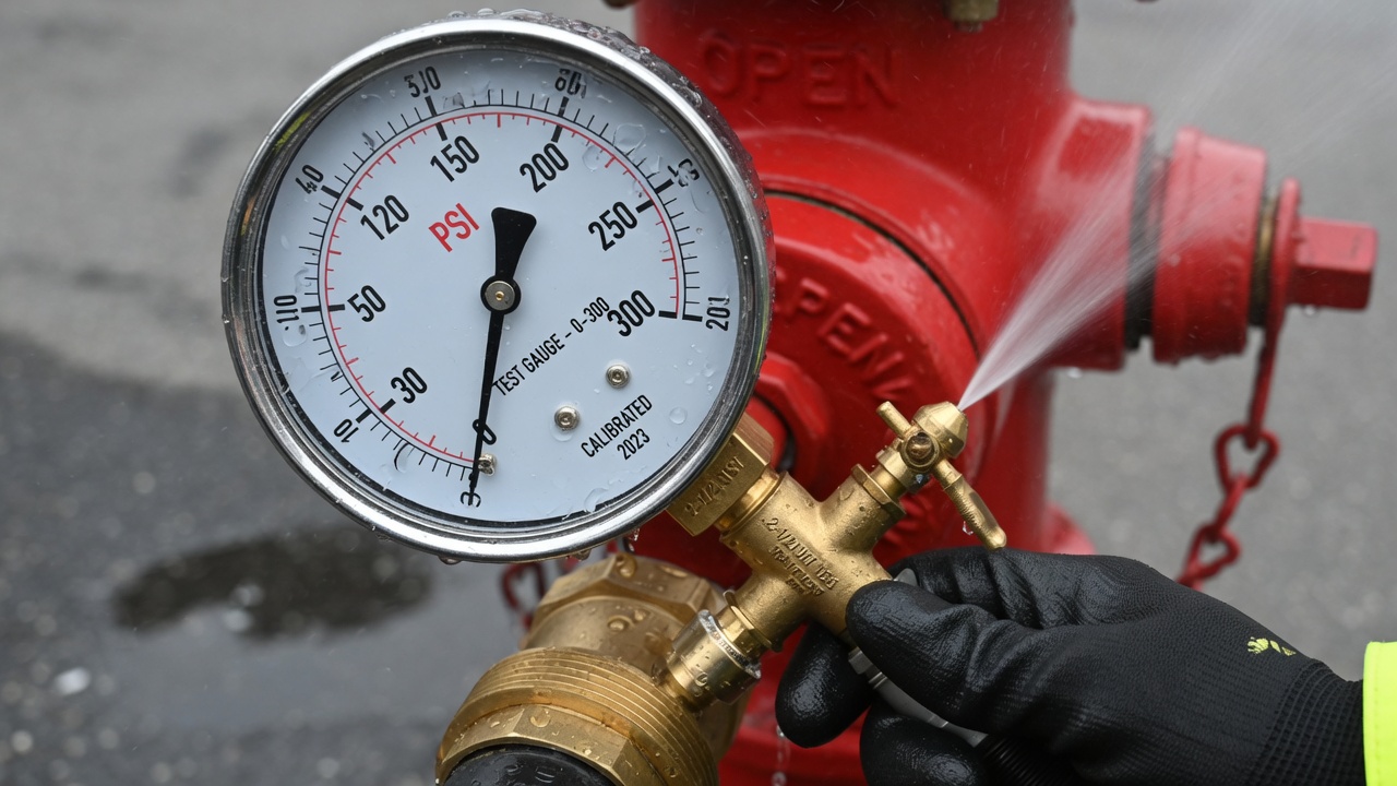
That usable drop starts with a clean static reading—the system’s normal operating pressure before any test outlet is opened. Record it at the residual hydrant itself, the same hydrant that will later show the pressure under load. With every test nozzle still closed and the system under ordinary demand only, the gauge captures the true baseline against which residual will be compared.
Mount a calibrated pressure gauge on a hydrant cap or unused outlet. Open the hydrant slowly, then crack the petcock or bleeder until a solid stream of water—not foam or sputter—emerges. Air trapped in the bourdon tube or connecting hose will make the needle dance or sit artificially high; bleed until the reading locks steady, then close the bleeder and note the value. That single number is the static pressure NFPA 291 expects you to carry forward into every later calculation.
Conditions that protect the baseline
Timing matters as much as technique. Avoid peak-demand windows—early morning industrial startups, irrigation cycles, or any nearby large draw that temporarily lowers system pressure. A depressed static reading shrinks the apparent drop and inflates the projected available fire flow, giving a false picture of capacity. If the only practical test window still carries some background demand, document the conditions so later reviewers understand the context.
Elevation also belongs in the record. When the gauge sits appreciably higher or lower than the main of interest, the reading includes a hydrostatic offset that does not reflect true main pressure. Note the vertical difference and correct to the hydraulic grade line of the pipe being evaluated; otherwise the static-to-residual drop—and every flow figure derived from it—will be systematically skewed.
Once the static baseline is locked in under quiet, ordinary conditions, the residual hydrant is ready for the load that will reveal how the system actually behaves. That next reading, taken while water is flowing, completes the pressure drop the Hazen-Williams projection needs.
Residual Pressure Under Load: Hitting the Drop Threshold
With flow hydrants opened, residual pressure is read at the same residual hydrant where the static baseline was taken. Keep the gauge on the residual hydrant’s outlet or cap outlet; do not move it to a flowing hydrant. Residual is simply the system pressure that remains while water is discharging elsewhere—the second leg of the pressure triangle and the value that, together with static, quantifies how far the main drops under load.
That drop must be large enough to make the subsequent Hazen-Williams projection reliable. NFPA 291 states that sufficient discharge should be achieved to cause a drop in pressure at the residual hydrant of at least 25 percent, or to flow the total demand necessary for firefighting purposes. A smaller drop leaves the test curve poorly defined and can inflate the calculated available fire flow at 20 psi. By contrast, AWWA M17 offers a simpler absolute floor: a drop of at least 10 psi from static to residual. Confirm which criterion your authority having jurisdiction expects before you begin; some utilities adopt the NFPA percentage, others the AWWA psi minimum, and a few require both.
How far to open the system
Open additional outlets or step up to larger nozzles only until the target drop is reached. Once residual has fallen 25 percent (or 10 psi, if that is the governing rule) and you have enough flow for the intended fire demand, stop. Driving residual still lower can push the system below usable firefighting levels, risk water-quality complaints from customers, or even collapse pressure enough to create backflow hazards. The goal is a controlled, diagnostic load—not a stress test that leaves the neighborhood dry.
Work through the following checks while the water is flowing so the residual reading stays clean and usable:
- Confirm the gauge is still fully bled and reading steadily before recording residual
- Verify no ordinary-demand valves were opened or closed after the static was locked
- Note the residual value the moment flow stabilizes, not during the initial surge
- Stop adding outlets the instant the required drop (25 % or 10 psi) is met
- Record residual alongside the static and the list of open outlets for the report
When residual is captured this way, the pressure drop is both large enough for a trustworthy projection and still high enough to keep the system in a realistic operating range. That pair of numbers—static and residual—now stands ready for the velocity-pressure measurement that will complete the discharge calculation.
Getting the Pitot Reading Right: Placement, Technique, and Coefficients

That velocity-pressure measurement is the pitot reading, and it is the final leg of the pressure triangle. Without a clean pitot value for every flowing outlet, the discharge figure Q has no reliable foundation—no matter how carefully static and residual were taken. The pitot tube converts the kinetic energy of the stream into a gauge pressure that, together with the outlet’s actual diameter and its discharge coefficient, yields the flow rate leaving each hydrant butt or nozzle.
Hold the pitot blade squarely in the center of the stream, roughly half the outlet diameter away from the face of the hydrant butt or nozzle, and keep the blade perpendicular to the direction of flow. Too close to the opening and the reading is distorted by turbulence at the vena contracta; too far out and the stream has already begun to break up. Angle the tube even a few degrees off perpendicular and the gauge under-reports velocity pressure. Take the reading only after the stream has stabilized and the residual hydrant has settled at its drop threshold.
Record a separate pitot pressure for every outlet that is flowing. Each outlet then receives its own discharge coefficient—typically higher for a smooth nozzle or playpipe than for a bare hydrant butt—so the individual Q values can be summed correctly. Never assume the outlet is exactly the nominal size stamped on the hydrant. Measure the actual inside diameter with calipers or a precision rule; even a small difference in diameter changes the calculated flow appreciably because diameter is squared in the formula.
When the stream is large or the test site is confined, slip a diffuser or short playpipe onto the outlet. The device straightens and controls the discharge, keeps the pitot blade in a predictable location, and protects both the gauge and nearby personnel from an uncontrolled jet. Once every flowing outlet has a documented pitot pressure, measured diameter, and appropriate coefficient, the three pressures are ready to be turned into discharge and available-fire-flow numbers.
From the Three Pressures to Discharge Q and Available Fire Flow at 20 psi
With pitot pressure, inside diameter, and coefficient recorded for every flowing outlet, the next step is pure arithmetic. Those three values feed the discharge equation that converts velocity pressure into gallons per minute; the resulting total test flow then combines with static and residual pressures to project available fire flow at the 20 psi residual that firefighting and backflow prevention both require.
Calculating discharge from each outlet
NFPA 291 gives the standard expression for flow from a single outlet:
where Q is discharge in gpm, C is the outlet coefficient, d is the actual inside diameter in inches, and p is the pitot (velocity) pressure in psi. A nearly identical constant of 29.84 appears in some references; either form is acceptable provided the same constant is used consistently for every outlet in the test. When more than one outlet is flowing, compute Q for each outlet separately—using its own measured diameter, pitot reading, and coefficient—then sum the individual results to obtain total test flow. That summed Q is the value carried forward into the available-fire-flow calculation.
Projecting available fire flow at 20 psi
Once total test flow is known, available fire flow (AFF) at a residual of 20 psi is obtained from the Hazen-Williams-derived relation:
Here S is the static pressure recorded before any test flow and R is the residual pressure observed while the hydrants were discharging. The exponent 0.54 reflects the friction-loss behavior of water in pressure pipes, so the formula correctly scales the measured flow up (or down) to the 20 psi residual that defines rated available fire flow.
What the Pressure Relationships Reveal About Capacity and System Health
Those discharge and available-fire-flow numbers are only as useful as the story the three pressures tell when you read them against one another. Static sets the baseline, residual shows how the system behaves under load, and pitot quantifies what actually left the outlet. Together they turn a field exercise into a diagnostic of both capacity and health.
The residual floor and a practical capacity floor
NFPA 291 expects residual pressure to remain at or above 20 psi during the test. That floor supports effective firefighting streams and protects the public supply against backflow contamination. In many evaluation contexts a recognized municipal hydrant is also expected to deliver at least 250 gpm at 20 psi residual for two hours. When either figure is missed, the hydrant—or the main feeding it—cannot be counted on for the demand the codes assume.
Reading the triangle for system problems
A large drop from static to residual relative to the flow produced usually points to closed or partially closed valves, undersized mains, or high friction losses along the supply path. Conversely, a weak pitot reading paired with a still-comfortable residual often traces back to the flowing outlet itself—wrong inside diameter, an incorrect discharge coefficient, debris, or a partially opened stem—rather than to the distribution system. Correcting the coefficient or clearing the outlet frequently restores the expected discharge without any main work.
The calculated available fire flow at 20 psi residual gives engineers a single, comparable number. It lets them stack measured supply against code-required fire flow and against the actual demand of the buildings the hydrant protects. That comparison drives decisions on main upgrades, additional hydrants, or pump sizing, and it feeds directly into ISO grading and sprinkler-system hydraulic calculations.
Keeping the data current
Public fire hydrants should be flow-tested every five years per NFPA 291 so that capacity figures stay current and color markings continue to reflect true performance. Between those cycles, any unexplained change in the static–residual–pitot relationship is itself a flag: something in the network or at the hydrant has shifted and deserves investigation before the next emergency call.
When static, residual, and pitot are captured correctly, converted with the proper formulas, and interpreted against these thresholds and patterns, raw gauge readings become valid discharge figures, a defensible available fire flow at 20 psi, and a clear picture of system health—precisely the outcome NFPA 291 is written to produce.